Gaus Battery Charger GBC24V10A-FCH-DCH
Automatski punjač za punjenje i regeneraciju baterija u invalidskim kolicima i skuterima
BATTERY CHARGER GBC24V10A-FCH-DCH
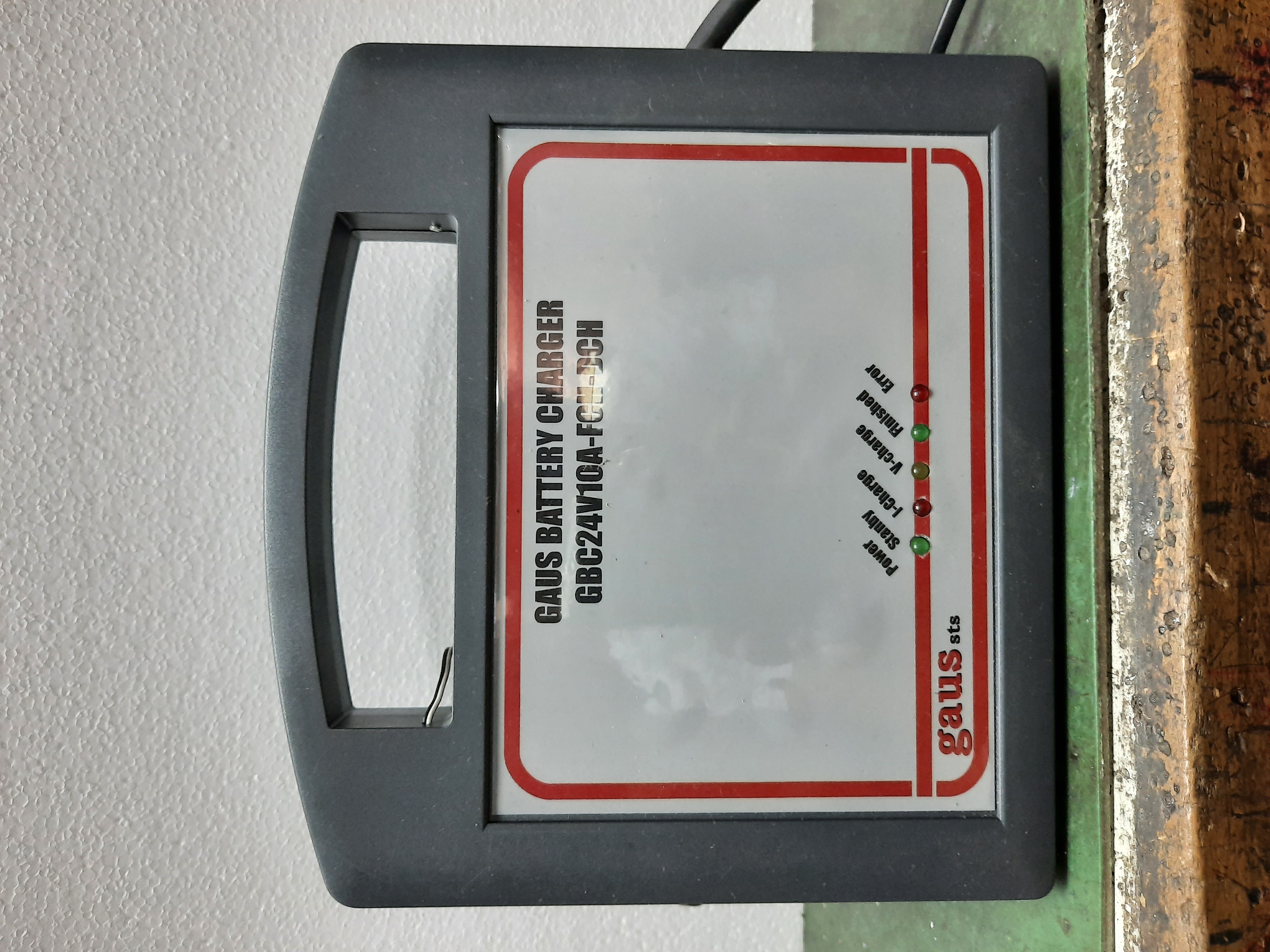
GBC24V10A-FCH-DCH (GBC-FCH-DCH) is a microprocessor device for charging, fast charging by GFCH method, conditioning and maintenance of lead-acid batteries of nominal voltages 6V, 12V and 24V at home. The GBC-FCH-DCH is a single-phase high-frequency intelligent constant voltage charger with current limitation. This means that the voltage at the output, i.e. on the connected battery, reaches with current that does not exceed the current limit, and after reaching the set voltage, the voltage level is maintained constant and the current drops as the battery is recharged. The magnitude of the charging current (current limit) is chosen depending on battery capacity or desired charging speed. Also, the value of the charging voltage is adjustable for various charging modes. Charging is voltage, current, time and capacity controlled and numerous protection measures have been implemented. GBC-FCH-DCH has RESET and MAINTENANCE operations. Namely, as the device supports charging and discharging operations, it is possible to perform the operation of discharging the battery with a constant current up to the level of 1.75V / Cell (5.25V, 10.5V or 21V) before the start of charging. Also, after the fast charge is completed, the device can enter the Maintenance mode by charging battery with a constant voltage of 2.25V / Cell (6.75V, 13.5V or 27V). As the device is microprocessor, with measurement of current, voltage, temperature of the cooler of semiconductor components and the case, it is possible to implement various algorithms. It is possible to change the voltage and current limits, condition the charging characteristics, pause, wait for the event (measuring Ah in the charge), condition the end of charging, etc. The energy part of the charger is the Mean-Well RPS-500 module. Thanks to the voltage charging characteristic, it is possible to charge without supervision, because there is no overcharging (overnight or on weekends). Also, if the mains supply fails during charging, the device automatically resumes charging with the parameters that were before the mains failure. The LCD display with 2x16 characters displays the values of current, voltage, time, capacity, warnings, irregularities, etc. and as well as setting the device through about 10 menus (selection of current and charging voltage, total Ah, charging duration, reset operation and / or battery maintenance ...). On the front of the device there are start (scroll) and stop (select) keys, R/S switch (Ready/Set), LCD display for indication. On the side of the device are the charger terminals and the input of the network cable. The charger is housed in a plastic case with a carrying handle. The charger version with automatic start and stop for 24V batteries has 5 LEDs for status indication. This version does not have an LCD display and keyboard. GAUS BATTERY CHARGER GBC24V10A-FCH-DCH has the following protections and features:1. there is no spark when connecting or disconnected charger terminals on the battery;2. natural air cooling;3. control of the minimum allowed voltage of the connected battery (disabled start for Ucell <0.5V-variable);4. temperature protection on the heat sink of semiconductor energy components;5. in case of mains power failure, after its re-establishment, charging automatically resumes with previously set parameters;6. blade slow fuse 20A 96VDC;7. slow fuse 20mm of T8A in mains circuit;8. soft start PWM modulator;9. delayed automatic start, soft start in charging input electrolytes;10. charger protection against short circuit at output terminals;11. protection against terminal drop during charging (paused device until battery voltage returns);12. protection against reverse polarity with disabled start;13. Voltage drop compensation on output cables;14. Voltage limit in charging 31VOption: GBC24V10A-FCH-DCH, Automatic start-stop, without LCD display and keyboard.
TECHNICAL CHARACTERISTICS
-type of voltage converter: single-phase high-frequency converter;-power supply 230V +/- 10%, detachable double cable, 1.8m long, IEC-60320 C7 connector, 47-63Hz 550W; max. output power 300W;-nominal input current: 2A; maximum starting current: 2.9A-instruments: LCD display 2x16 characters, ammeter 0-20.00A, voltmeter 0-40.00V, temp1 –99 to 99C, or 5 LEDs-length of connecting cables with lead terminals: 2m, cross section 2.5mm2, XLR male connector Neutric NC3MX-B-operating temperature: 5 to + 40C, control of maximum inside temperature, 20 degrees above ambient temperature-storage temperature: -40C up to 65C-consumption in standby mode less than 0.5W-maximum reverse current to battery less than 1mA-The time to charge the battery (C20 less than 60Ah) to 80% in automatic mode is less than 6 hours -in version with automatic start-stop delay of 2 seconds in start after detecting battery connection-in version with automatic start-stop the battery shall be recognized to be defective when CC (constant current i.e. bulk charge) phase needs longer than 12 hours-drop withstanding (un operated) drop height 0.80m is 10 drops to the most critical side, no malfunction, no danger for life and limbs-MTBF 194.1khrs min MIL-HDBK-217F (25)
|
Charging current |
0.2-10A Cn/10, Cn/5... max 10A +/-5% |
|
Battert type |
6, 12, 24V (2x12V); Cn od 33Ah do 100Ah, Sb-Sb, Sb-Ca, Ca-Ca, AGM, Gel |
|
Charging voltage range |
3-33V (maximum available) |
|
Output voltage |
6V, 12V, 24V (2.47, 2.57, 2.67V/Cell, 2.20-2.75V/Cell setting step 0.01V/Cell) |
|
Capacity |
Charging one or two 12V batteries Or 3, 6 or 12 cells connected in series |
|
Accuracy |
Better than 2% |
|
Resolution |
20mA and 40mV (less than 0.5%) |
| Current ripple |
0,1A max |
|
Output voltage ripple |
<20mV, 0.2% |
|
Energy circuit |
MOSFET transistors, ultra fast diodes |
| operating frequency |
PWM 100kHz, PFC 90kHz |
| efficiency |
94% |
|
Cooling |
Temperature controlled forced air, 3 speed fan, >45C speed1, >60C speed2, |
|
Controll characteristics |
Constant voltage charger with current limit IU |
|
Controll variables |
Current, voltage, capacity, duration... |
|
Displaying |
LCD display 2x16 characters with back light or 5 LEDs |
|
Controll elements |
start and stop buttons, switch Ready/Set, or LED diodes Power/Standby, I-charge, V-charge, Finished, Error |
|
Alarm High Current |
Ich>12A |
|
Alarm High Voltage |
Vch>30.8V |
|
Max. Output voltage |
Voutmax=31V |
|
Operation RESET |
Idch is Ich/4, up to 1.75V/Cell (5.25V, 10.5V or 21V) |
|
Operation MAINTENANCE |
Umaintenance (float) is 2.25V/Cell (7.2V, 13.5V or 27V) |
|
Housing |
Plastic ABS box |
|
Dimensions (WxHxD) |
225x210x85mm |
|
Weight |
1.6kg |
GBC24V10A-FCH-DCH complies with following standards:
- LVD – Electrical safety testing according to standard(s)
EN 60335-2-29:2004 + A2:2010 + A11:2018 for use in conjunction, EN 60335-1:2012 + A11:2014 + A13:2017 + A1:2019 + A14:2019 + A2:2019 including test report
- EMC – testing according to standard(s) EN 61000-6-4:2007+A1:2011, EN 61000-6-2:2005, EN 61000-3-2:2014, EN 61000-3-3:2013 including test report
|
|
Energy module complies with:
|
MDD Directive (93/42/EEC) |
||
|
EN60601-1:2006+A11+A1+A12 TUV certificate No: TA 50430169 |
||
|
EMI (Electro-Magnetic Interference) |
||
|
Conducted emission |
EN55011:2016/A1:2017 |
Class A(for Class II);Class B(for Class I) |
|
Radiated emission |
EN55011:2016/A1:2017 |
Class A |
|
Harmonic current EN61000-3-2:2014 |
||
|
Voltage flicker EN61000-3-3:2013 |
||
|
EMS (Electro-Magnetic Susceptibility) |
||
|
EN60601-1-2:2015 |
||
|
ESD air |
EN61000-4-2:2009 |
Level 4 15KV |
|
ESD contact |
EN61000-4-2:2009 |
Level 4 8KV |
|
RF field susceptibility |
EN61000-4-3: 2010 |
Level 3 10V/m(80MHz-2.7GHz) |
|
RF field susceptibility |
EN61000-4-3: 2010 |
Table 9 9~28V/m (385MHz~5.78GHz) |
|
EFT bursts |
EN61000-4-4:2012 |
Level 3 2KV/100KHz |
|
Surge susceptibility |
EN61000-4-5:2014 |
Level 4 2KV/Line-Line |
|
Surge susceptibility |
EN61000-4-5:2014 |
Level 4 4KV/Line-FG |
|
Conducted susceptibility |
EN61000-4-6:2014 |
Level 3 10V |
|
Magnetic field immunity |
EN61000-4-8:2010 |
Level 4 30A/m |
INDICATION
From the bottom to the top:
- Green LED STANDBY
- Red LED bulk charge (constant current) and constant voltage charge CH1 and CH2, I1U1
- Yellow LED constant current charge and constant voltage charge CH3 and CH4, I2U2
- Green LED charge FINISHED
- Red LED ERROR bad battery, bulk charge >12h or overheat of the charger.
GBC12-24V10A-FCH-DCH Charging Curve
The automatic start and charge rate functions have been implemented. Namely, when the device recognizes the battery connection, the charging process with preset parameters is automatically started within ten seconds. If the battery is disconnected during charging, charging stops. Each switching ON of the device (the mains plug is plugged into mains) is followed by an automatic start of charging if a suitable battery is connected. In a “poofer” connection, charging is activated when the battery voltage drops below a certain level due to self-discharge or consumer consumption.Charging curve and parameters for auto start are: NoCell = 12 for 24V battery:Phase 1. (CH1), LED I1U1 RED LED DIODE ON§ Current limit in auto start I1=10ADC§ End of phase 1 2.4V/Cell U = 28.8V or T> 12hPhase 2. (CH2) LED I1U1 RED LED DIODE ON§ Voltage limit U1=2.4V/Cell or 28.8V§ Current limit I1=10ADC§ End of phase 2 I 12hPhase 3. (CH3), LED I2U2 YELLOW LED DIODE ON§ Iconst I2=2.5A up to battery voltage of 2.43V/Cell 29.2V or 2.4V/Cell 28.8V§ End of phase 3 U=29.2V (28.8V) or T>12hPhase 4. (CH4), LED I2U2 YELLOW LED DIODE ON§ Voltage limit U2=2.43V(2.40V) / Cell or 29.2V(28.8V)§ Current limit I2=2.5ADC§ End of phase 4 condition dv/dt or Uconst=U2 for 3hours or I<0,30A. If FLOAT is not SET, charger stops.GREEN LED DIODE FINISHED/FLOAT turns ON, § DefTimer maximum charging time 15h, 4 stage charging is followed by FLOAT stage, charging stops even in FLOAT stage after 15h from the start of charging.§ Maintenance FLOAT YES, 2.25V / Cell or 27V (MAI), LED Finished/U3-Float GREEN LED DIODE ON§ Battery presence threshold from 0V to over 5V§ Recharging thresholds (poofer) NO, Ubatt> 8V and Ubatt <24.9VRED LED DIODE ERROR turns ON in case of temperature alarm (over heating) or if bulk charge takes more than 12 hours (bad battery).GREEN LED DIODE STANDBY is turn ON when main supply is ON and battery is not connected.Automatic start is disabled if manual charging (parameter setting) is in progress and if the device is in SET mode (active settings menus on the LCD display). This note applies to the charger variant with LCD display and keyboard.
DEVICE PLATE
Manufacturer: GAUS-S.T.S. d.o.o. Belgrade, Jurija Gagarina 167/41, 11070 Novi Beograd, Belgrade, Serbia, gaus.sts@gmail.com, www.gaus-sts.com

